Climate change affects us all. Many of our projects are concerned with “climate-neutral” energy provision, with the aim of reducingCO2 emissions. According to the IPCC (Intergovernmental Panel on Climate Change), the 1.5°C target of the Paris Agreement cannot be achieved through measures to reduceCO2 emissions alone; net zero and “negative”CO2 emissions are also required.
The CONENGA Group has been dedicated to the former for many years with great success (Magnes-IT, decarbonization, process engineering innovations,…). But we are also working intensively on the second point, which has only become more and more concrete in recent years, in the area of innovativeCO2 capture options, also known as “carbon capture” (CC). This refers to the technical separation of carbon dioxide from exhaust gas streams before it is released into the atmosphere.
Why carbon capture?
The natural carbon cycle, in whichCO2 sources andCO2 sinks(reservoirs) are balanced, is thrown out of balance by human-induced carbon dioxide emissions. Theexcess CO2 is mainly produced during the thermal conversion (combustion) of fossil and biogenic organic fuels, but also during biotechnological processes such as bioethanol production.
This imbalance increases the atmospheric CO₂ content. As a greenhouse gas, CO₂ indirectly causes the earth’s temperature to rise, as the heat radiation reflected from the ground can no longer escape sufficiently from the atmosphere.
However, energy plants that produce heat and electrical energy are still needed. This is why CO2 capture (CC) comes into play: carbon dioxide can be captured from the flue gases of heating plants to minimize further greenhouse gas emissions in the atmosphere.
We are currently focusing on the topic of carbon capture and utilization / storage in biogenic-fired plants. Various technologies are being considered for this purpose.
Carbon capture technology overview
Various processes at different stages of development are available for CO₂ capture from flue gases.
- In pre-combustion processes, the CO2 is captured before the actual combustion process. For this purpose, the fuel is first converted into synthesis gas and then captured.
- In oxy-combustion, the fuel is burned with almost pure oxygen instead of air.
- In the post-combustion process, the fuel is burned conventionally; the carbon dioxide contained in the exhaust gas is then selectively captured.
Post-combustion separation technology is particularly interesting for existing systems, as it can be applied after the combustion process and can be retrofitted. Accordingly, this process is also the most relevant for the needs of our existing customers.
Post-combustion in detail
In the case ofCO2 capture from flue gas, this process is used because the technology can be adapted and retrofitted to most incineration plants. As the CONENGA Group, we check the basic requirements and parameters for the best separation efficiency for plant operators and then evaluate which technology is best suited for the respective site.
Technologies used
Two selected variants from the wide range of post-combustion technologies are presented here: amine scrubbing, which is already in use on an industrial scale, and TSA (temperature swing adsorption), which is still at the development stage but offers particular advantages in terms of handling and energy efficiency.
- CO2 absorption(amine scrubbing)
Amine scrubbing is the best known and most established process forseparating CO2 from flue gas. Amines react with theCO2 to form water-soluble components and are thus separated from the flue gas.
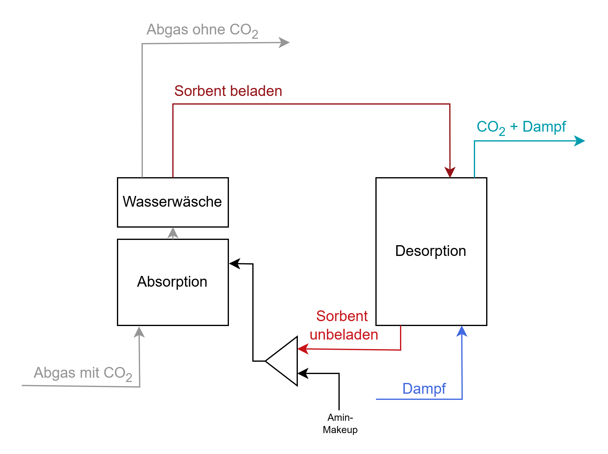
Process flow diagram of a typical system for amine washing
As shown in the illustration, the plant primarily consists of two units – the absorber, whereCO2 is absorbed from the acidic exhaust gas, and the stripper, where theCO2 is desorbedat higher temperatures and then liquefied for further use. The advantage of amine scrubbing is the maturity of the technology and the high separation rate, while the disadvantage is the high energy requirement to achieve high purity levels. [1], [2], [3]
- CO2 adsorption(Temperature Swing Absorption)
Temperature Swing Adsorption (TSA process) is another technology that we at the CONENGA Group are working intensively on. This involves the chemisorption of carbon dioxide on solids. This requires highly selective sorbents.
The following figure shows the main material flows of a multi-stage TSA fluidized bed system consisting of two units as an example of an adsorption process. In the adsorber (left), the carbon dioxide binds to the particles, which are then conveyed to the desorber (right). There, theCO2 is desorbed at high temperatures with process steam and then further processed. [4]
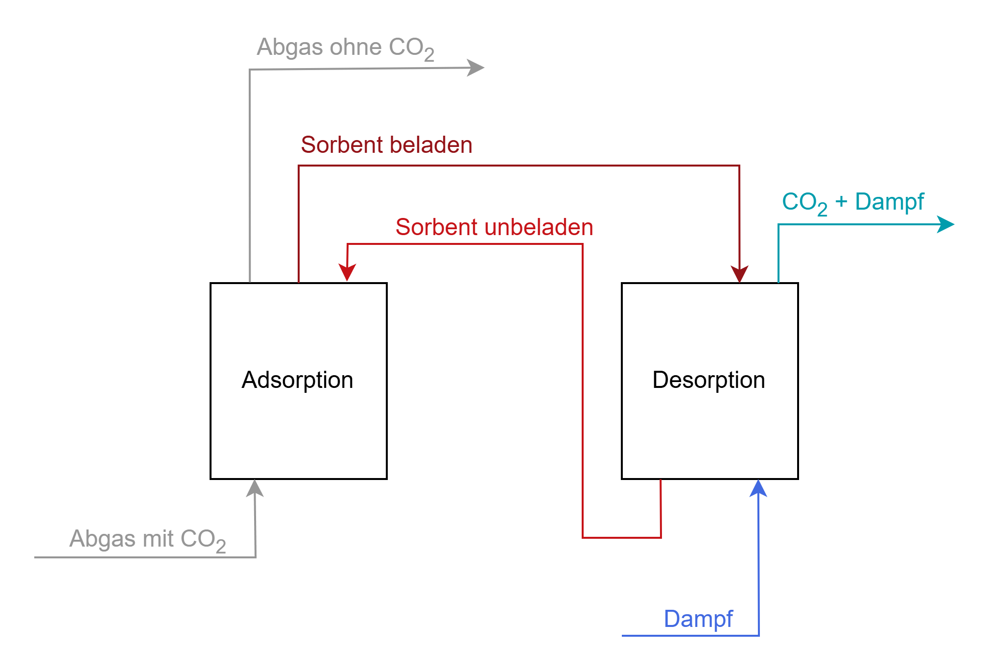
Block diagram showing the main material flows of a multi-stage TSA fluidized bed system forCO2 separation from the flue gas.
Adsorption processes can be implemented not only as TSA, but also as PSA (Pressure Swing Adsorption) or as a combination of both technologies. Furthermore, the technology can be designed not only as a fluidized bed reactor but also as a fixed bed reactor. [5], [6]
Status Quo
The degree of maturity for adsorption technologies in CO2 capture applications has not yet reached the industrial standard. However, the technologies, especially TSA, are promising in terms of achieving high purity levels and energy consumption. [4] An economic advantage arises above all at locations where heat is available at the appropriate temperature level.
We are therefore pursuing this concept intensively in research projects in order to be able to provide this practical technology to our customers with fulfilled site requirements.

About the author:
Our colleague Sabrina Kröhnert gives us a compact insight into research and practice at the CONENGA Group: As part of the FFG-funded BioFizz research project, she looked into the topic of CO₂ capture (carbon capture, CC) and also dedicated her master’s thesis to this topic. Read more about the research project in this blog post.
Sabrina Kröhnert
CONENGA Group
Sources:
[1] J. D. Figueroa, T. Fout, S. Plasynski, H. McIlvried, and R. D. Srivastava, “Advances in CO2 capture technology-The U.S. Department of Energy’s Carbon Sequestration Program,” Int. J. Greenh. Gas Control, vol. 2, no. 1, pp. 9-20, Jan. 2008, doi: 10.1016/S1750-5836(07)00094-1.
[2] Y.-D. Hsiao and C.-T. Chang, “Efficient multi-objective optimization and operational analysis of amine scrubbing CO2 capture process with artificial neural network”, Int. J. Greenh. Gas Con-trol, vol. 138, pp. 104242, Oct. 2024, doi: 10.1016/j.ijggc.2024.104242.
[3] E. Pancione, A. Erto, F. Di Natale, A. Lancia, and M. Balsamo, “A comprehensive review of post-combustion CO2 capture technologies for applications in the maritime sector: A focus on adsorbent materials”, J. CO2 Util, vol. 89, pp. 102955, Nov. 2024, doi: 10.1016/j.jcou.2024.102955.
[4] F. Zerobin and T. Pröll, “Concentrated Carbon Dioxide (CO2 ) from Diluted Sources through Continuous Temperature Swing Adsorption (TSA)”, Ind. Eng. Chem. Res., vol. 59, no. 19, pp. 9207-9214, May 2020, doi: 10.1021/acs.iecr.9b06177.
[5] H. Si et al, “Analysis on temperature vacuum swing adsorption from wet flue gas carbon cap-ture by using solid amine adsorbent with co-adsorption equilibrium models”, Fuel, vol. 380, pp. 133171, Jan. 2025, doi: 10.1016/j.fuel.2024.133171.
[6] P. A. Webley, A. Qader, A. Ntiamoah, J. Ling, P. Xiao, and Y. Zhai, “A New Multi-bed Vacuum Swing Adsorption Cycle for CO2 Capture from Flue Gas Streams,” Energy Procedia, vol. 114, pp. 2467-2480, July 2017, doi: 10.1016/j.egypro.2017.03.1398.

Sabrina Kröhnert, MSc, ist Process Engineer bei der CONENGA Group und spezialisiert auf Verfahrenstechnik mit Fokus auf nachhaltige Energie- und Umweltlösungen. Ihr Schwerpunkt liegt auf der Optimierung thermisch basierter Energiebereitstellung und Energieverwendung sowie der Mitwirkung an Innovations- und Entwicklungsprojekten zur Steigerung von Effizienz und Nachhaltigkeit in industriellen Prozessen.
Ihr Masterstudium der Bio- und Umwelttechnik mit Schwerpunkt Umwelttechnik absolvierte sie an der FH Wels. Bereits während ihres Studiums sammelte sie umfassende praktische Erfahrung in Forschung und Industrie. Dazu zählen Tätigkeiten als wissenschaftliche Mitarbeiterin in den Bereichen Mikroalgenkultivierung und digitale Sensorsysteme zur frühzeitigen Erkennung von Waldstress, sowie ihre Bachelorarbeit im Bereich Deponiebau in Zusammenarbeit mit der PORR Umwelttechnik GmbH.
Weitere Praxiserfahrung sammelte sie als technische Mitarbeiterin bei der Fahrkraft Industrieplanungs- und Beratungs-GmbH. Durch ihre Kombination aus wissenschaftlicher Expertise und industrieller Anwendungskompetenz bringt sie fundiertes Know-how in den Bereichen Umwelttechnik, Energieeffizienz und nachhaltige Prozessoptimierung ein.